Quantcast
Channel: Digital I/O topics
Viewing all 2183 articles
Browse latest View live

Current measurement using NI 9227

$
0
0

Hello.


I am using NI cRIO 9012 with I/O modules NI 9472 (DO), NI 9227 (AI current), NI 9225 (AI voltage) in Scan Interface mode. I want to aqcuire current through a resistor using NI 9227 and implement PI control. I think I made the wiring as per the manual of NI 9227 but unable to acquire any measurement.


Im afraid I am making a mistake in connections of the 9227 to the resistor. 


Kindly help me. Are there any precautions and necessary steps I need to take while connecting it? Any necessary steps to be taken while using the analog pin in the VI.


Thanks in advance.


Lahari


USB Microphone DeviceID

$
0
0

I've got a system with a couple GigEVision cameras and a USB microphone.  Sometimes there are additional IP cameras (axis, etc.), so I used the enumerate cameras function to filter for the cameras I want to use without any user input.  I'd like to do the same for a USB microphone, but I'm not sure what to use.  If I use  Acquire Sound, the configure dialog that comes up lists every microphone and the device ID for that microphone, but I'm not sure how to access that programatically.  One alternative would be if there were a config file that would allow me to set a static device ID. 


Thanks,

Brendan

NI 6585 loop back and Single cycle time loop.

$
0
0

I am using a NI 6585/PXIe-7961 I am currently developing an application where I am doing source syncrounsu communicaiton.  At the moment I do not have the hard ware that is going to be transmitting to me.  I am trying to set up a situation where I can just do a loop back on myself and send a signal out of one connector and recieve it in another.  The issues I am having is that in trying to simulate how the set up will be once I get real harddware is that when I export a clock from connector B I can't use that clock on connector A becuase it is going to the same line in connector A where a clock is exported. Is there anyway to change the line that the clock is exported on and then use that line as a clock signal?   


Second when I use a clock external or internal with a single cycle time loop is the start of each itteration of the loop on a rising clock edge?

Digital Output Freeze

$
0
0

Hi there,


We have a PXI RT system with a PXI-6515 card. This card has been operating fine with the program until the past 1 month. One of the digital output channels freezed, where the signal stayed on even though we have send the command for the signal to turn off via DAQmx and via MAX. This was verified using a multimeter and a third-party PLC. We changed the signal to another DO channel, the problem goes away but yesterday, it recurs on the new channel. Any reason why? 
 
Thanks.

pxie-6556 delay between 2 dio

$
0
0

Hi forum .

I have PXIe-6556, I need OUT ,in 2 DIOs wires, square signals and I need options to change delay between that signals .

I tried to run examples but without success.

I need it as simple as possible , 2 OUTs with option to control the delay .

If anyone has done something similar ? 


Thanks .

NI 6585 clock to host

$
0
0

I have an NI 6585/PIXe-7691R is there was a way to get a clock signal to a host VI so that I can graph the clock along with some other IO in a digital waveform graph? 

error 201105 en el módulo 9425 aún reiniciando

$
0
0

Hola.

Estoy teniendo un problema con 2 programas escritos en C que acceden al chasis NI cDAQ-9174 el cual tiene los módulos NI 9215 (BNC), NI 9472, y 2 modulos NI 9425. Uno de los programas, llamemosle A, accede a los modulos 9215, 9472 y a uno de los 9425; el otro programa, llamemosle B, accede al otro modulo 9425.

Todo funciona bien hasta que cada cierto tiempo el modulo 9425 que utiliza el programa A empieza a recibir todas las señales en 0 sin recibir ningún codigo de error por parte de la API de National, algunas veces el otro modulo 9425 que utiliza el programa sigue funcionando correctamente y otras veces sufre el mismo problema.

Algunos de los sensores conectado a la 9425 tiene señal 0 cuando estan activados y 1 cuando estan desactivados por lo que recibir todas las entradas en 0 es un claro sintoma de que algo anda mal.

Luego de haber detectado el problema se cierran todos los programas, se resetean los modulos y chasis desde el Measurement & Automation Explorer, (M&AE) se reinicia la máquina y se vuelve a resetear todos los modulos (por las dudas) y se toman muestras desde el "Test panel" de M&AE. El muestreo sigue dando todo en 0 y cuando se detiene el muestreo y se realiza un "self test" aparece el error 201105 pero no hay nadie utilizando el hardware.

La única solución a esto es quitarle la corriente al chasis.

¿A alguien le paso esto? ¿Tiene solución?

Agradecería si alguien me puede contestar o darme indicaciones de dónde buscar la solución.

How can I use my NI 9401 to send a 5V signal to a solid state relay?

$
0
0

To start off, I am a complete novice to LabVIEW and I am working on my senior capstone project. Please, bear with me and I will try my best to help you help me.


I am wanting to use my NI 9401 to send a voltage to a solid state relay so that I can control the temperature of a heating element. Ideally what I want to do is:


1. LabVIEW sends voltage to relay.  

2. Relay turns on.

3. Heating element reaches desired temperature.

4. LabVIEW does some sort of pulse to maintain that temperature.


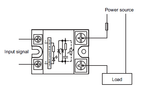
Right now I have one wire set inside of DIO 4 (or pin 20?) because I have read that 4:7 are for outputs. I also have another wire in the first COM slot (pin 1?).  I believe that these two wires will be placed in the "input signal" spots on the diagram below. 


Digital in not readable: ContReadDigChan_ExtClk example bugged

$
0
0

Hello everyone,


again I need to ask you guys for help as I can't figure out how to continiously read a digital input. I am altering a software which has been running fine for over a year. The software is written in C# using the applicable librarys. The card I am using is USB-6210.


What I am already doing (works perfectly well):


  • Read two analog in channels
  • Read quadrature encoder via ctr0
  • Synchronize the acquisition of the analog tasts by using a clock task on the freqout pin
  • Get all the data


What I am failing to do:


In addition to the analog ins, read another digital in. Here is the error message:


ni error.PNG


What i tried after the ContReadDigChan_ExtClk rebuild in my software didn't work:


  • Rebuild my 4 tasks in MAX. The problem: you can't access the /freqout pin in a MAX task. It works perfectly in the device self-test but there is no option to use it in a DAQmx Task
  • Using the example ContReadDigChan_ExtClk. Problem is this crashes with the same error as my application.

I also looked for the error here in the forums. All I could find is a post from 2006: http://forums.ni.com/t5/Digital-I-O/VB-2005-amp-ContReadDigChan-ExtClk-Example-Exception-Error/td-p/458376

But the user here was obviously using a wrong card. My card supports generation the clock (demonstrated by my working project) so this can't be the error.


I am somewhat disappointed that the given sample is bugged :smileysad:


Would really appreciate help on this!


Best

nano

How should Sensirion SHT71 be wired to SCB-68A connector block?

$
0
0

Hi all,

I just got a Sensirion SHT71 for humidity measurement. I am new to digital I/O field so I feel unclear about how to connect this sensor to the DAQ. 

The DAQ I am using is PXI-6225 hooked up with a SCB-68A connector block. 


And the sensor has 4 pins (1-SCK: Serial Clock, 2-VDD: Source Voltage, 3-GND, 4-DATA (bidirectional))

Detailed manual can be found here http://www.sensirion.com/nc/en/products/humidity-temperature/download-center/?cid=8574&did=68&sechash=2f9d5b5c


So I am wondering what are the corresponding connectors on SCB-68A to those pins of the sensor. I can see the GND goes to the D GND for sure and the VDD is supposed to be connected to +5V. And I am not sure to which two connectors SCK and DATA should connect...

Reference label of SCB-68A can be found here: http://digital.ni.com/public.nsf/$CXIV/ATTACH-AEEE-8ZRTL5/$FILE/S_Series.pdf


Thanks.


Is USB-6501 (with 24 digital IO) compatible with Signal software from Cambridge Electronic Design (CED)

$
0
0

I am working with Cambridge Electronic Design (CED) hardware and software. http://ced.co.uk/. I have the CED 1902 amplifier, the Micro 1401 data acquisition unit, and Signal software.


My problem is a lack of digital outputs -- the Micro 1401 only has 2 digital outputs.


Is the NI USB-6501 compatible with Signal software? That is, will Signal recognise the digital outputs of the USB-6501 and control these dig outputs the same way that it recognises and controls the dig outputs on the Micro 1401?


Thanks in advance.

Digital Relays to DAQ

$
0
0

Hi, 

I have quick question you. Can I connect multiple digitals relays to single scb-68 terminal block (DAQ is : PCI 6321)?

Through Labview, I want to turn on or off each of these relays.  Is it technically possible? becuase, I never connected more than one sensor to scb-68. 


The each of the relay acts as a binary switch to a brushed dc motor (motor voltage 3-12 v and rpm : 11.5 krm with weight < 80 grams). The dc motors will receive power from external dc power supply unit.  So the power for the relays (I am thinking) must be from DAQ. But I know DAQ can supply only very very less current. I am trying to source out if I can find relays that run with very current (which could be supplied by the DAq itself) Can you suggest me if this is possible? And also any information or source for the required digital relays would be lot helpful.


Thanks

MSC

wireless digital switch

$
0
0

I want to connnect two on/off switches to a wireless DAQ, and have the wireless DAQ connects to a corporate wireless network.  Then, users can use their internet browser to view the status of these switches.  What is the cheapest way of doing that?  I don't want to add a host PC or real time target.  I looked at the wireless DAQ and WSN, but I don't think they are overkill and requires a host.  I just want to tell the rest of the company the availability of two pieces of equipments.  Any idea?  

How to reduce PXI-6509 crosstalk?

$
0
0

I have a PXI-6509 board in a PXIe-1073 chassis, with an RG1005050 cable.  I'm using the DIO pins exclusively for digital output.  I'm controlling the 6509 using DAQmx and MS Visual C++.


When I set certain bits high, I'm getting "glitches" or crosstalk with amplitude of 3-4 Volts and duration of 20-50 nanoseconds.  The crosstalk is triggering my Device Under Test (DUT) and my measurement (oscilloscope) at undesired times.  I'm wondering if there's a DAQmx setting to slow down the rise and fall times on digital outputs, and thus reduce the crosstalk.


Thanks for any help or suggestions!


Several tasks addressing the same DO port

$
0
0

Hi,


I'm building a software program based on plugins.

All these plugins interact with DIOs.


When the plugin is loaded in memory, it loads its configuration and create a task to control/read DIOs port on C-series modules (9476 and 9425) placed in a cDAQ chassis.

If the task pointing on a module is already built, plugins reuse the already created task instead of creating a new one. All DIOs tasks are not synchronized on any clock, they only return the port state when necessary (software timed).

Actions on DO are always the same : Read current DO port state, apply mask and pattern on the read value and apply new calculated state on the DO port.


According to the plugins used, it might be possible that several of them will want to access the same DO port of a module at the same time. Is there something like a round-robin mechanism which handles this kind of situation ? Or should I create a semaphore to reserve the access the DO port one plugin after the other ? If an explicit semaphore is required, can it be embedded in the DAQmx task (or specific DAQmx function) or should I use standard semaphores available in LabVIEW ?


Thank you for your help !


daqmx installation to be used in visual basic 2008

$
0
0

I plan to use PCI-6509 Digital IO in visual basic 2008. I installed NIDAQmx9.5.1.f2.

After installation, NIMax can detect the hardware(PCI-6509) successfully. NIMax was installed when DAQMX was installing.


But In VB2008>project>add reference>.NET, I can not see NationalInstruments.daqmx.

So I can't add it to my vb2008 program's reference.My program use PCI-6509 to control relay.


my PC has window 7 64bit operating system and the following .NET has been installed already.

Microsoft.NET compact Framework 2.0 SP2

Microsoft.NET compact Framework 3.5


Please let me know if you have any idea?

Thank you in advance.


Issues with Matlab Data Acquisition Toolbox / NI-6501 Error: -200324

$
0
0

Hi,


I'm trying to run an NI-6501 through Matlab R2012b.   I'm using Data Acquisition Toolbox ver 3.2 and I'm running on Windows 7 / 64 bit.


I'm using session based interfaces:


Code so far:


%Verify that NI 6501 is plugged in.

%Should get a readout in the MATLAB screen that shows

%USB connection for NI 6501.


deviceString = daq.getDevices;

niObj = deviceString.ID;


%Establish connection


session = daq.createSession('ni')

warning off;

session.addDigitalChannel(niObj, 'Port0/Line0:7', 'OutputOnly');

session.addDigitalChannel(niObj, 'Port2/Line0:7', 'OutputOnly');

warning on;

controlMatrix = ones(1,16);


However when I try to set any outputs, I get errors:


session.queueOutputData(controlMatrix); --> queueOutputData is disabled because the session contains channels that do not support clocked operations.


>> session.outputSingleScan(controlMatrix);
NI Error -200324:
NI-DAQmx is unable to communicate with the device. Make sure the device is present in and
accessible to the system, is not currently being reset, and is not reserved by another driver
such as Traditional NI-DAQ (Legacy).
Task Name: _unnamedTask<37>

Status Code: -200324


Can anyone offer any suggestions?

Thanks

Output clock on general data pins using 6536?

$
0
0

Hello,


   I have an NI PCIe-6536 DIO card, using latest DAQmx drivers, using C language.


   I would like to output the sample clock (or other clocks) on a few general DIO pins, like port0/line3 and port1/line6.


   What's the best way to accomplish this?  Is it best to use Task-based or 'independent' signal routing?  Am I missing a code example that will make my question seem even dumber?


   This seems to work when I try to connect to PFI4:


DAQmxErrChk(DAQmxConnectTerms("/Dev1/DO/SampleClock","/Dev1/PFI4",DAQmx_Val_DoNotInvertPolarity));

  However when I try to also connect that terminal to port0/line3 I get an error:

DAQmxErrChk(DAQmxConnectTerms("/Dev1/PFI4","/Dev1/port0/line3",DAQmx_Val_DoNotInvertPolarity));

Destination terminal to be routed could not be found on the device. Make sure the terminal name is valid for the specified device. Refer to Measurement & Automation Explorer or your hardware documentation for valid terminal names. Source Device: Dev1 Source Terminal: PFI4 Destination Device: Dev1 Destination Terminal: port0/line3 Status Code: -89121


   This error sounds like a trivial terminal name issue, but I'm fairly sure the terminal name is Ok.  Am I wrong?


I have tried another method using task-based signal routing and DAQmxExportSignal, which also returns an error:


DAQmxErrChk(DAQmxCreateTask("",&clockTask));
DAQmxErrChk(DAQmxCreateDOChan(clockTask,"Dev1/port0/line3","SCLK",DAQmx_Val_ChanPerLine));
DAQmxErrChk(DAQmxExportSignal(clockTask,DAQmx_Val_SampleClock,"/Dev1/port0/line3"));
DAQmxErrChk(DAQmxStartTask(clockTask));

Sample Clock Output Terminal requested is not supported given the requested Timing Type. To use the requested Timing Type, do not set the Sample Clock Output Terminal property. NI-DAQmx automatically selects a compatible Sample Clock Output Terminal. To use the requested Sample Clock Output Terminal, select a different Timing Type. Property: DAQmx_SampTimingType Requested Value: DAQmx_Val_OnDemand Property: DAQmx_Exported_SampClk_OutputTerm Requested Value: /Dev1/port0/line3 Task Name: _unnamedTask Status Code: -200910


  I'm guessing my port0/line3 needs to be configured differently, but I'm not sure which timing type to set.


So my question is if this is even possible, I'm just doing it wrong?   Or is it true that I can only output a clock on PFI4 and PFI5 pins?


As a follow up, should I instead be using the following function to export the sample clock?

DAQmxErrChk(DAQmxSetExportedSampClkOutputTerm(taskHandle,"/Dev1/PFI4"));

Also I see these functions: 

DAQmxSetExported10MHzRefClkOutputTerm


DAQmxSetExported20MHzTimebaseOutputTerm


Can I use these to output to port0/line3 and port1/line6?   I have some flexibility in clock speeds I can use, but curious if I can output 3 different clock speeds?

Also I could work out a method to use external clocks from other devices, but would prefer to maximize my usage of the internal clocks on the 6536 to keep the hardware requirements as simple as possible.


Thanks so much for any advice or insights!
Increasing Digital Output Current on USB-6001 with ULN2003A

$
0
0

I am controlling a stepper motor driver and the current required on the digital inputs of the stepper driver is around 11mA (at 5V).  My USB-6001 is not capable of outputting that high of a current.  I have seen people using the ULN2003A to control relays and it looks like it should work for my application.  Will this work and then can I use the 5V output to go to the ULN2003A since it can output 150mA.  To wire up the ULN2003A would I use the 5V output and put the positive on the COM?

How can I send digital Output at faster rate than 1ms period?

$
0
0

Hi!

I'm using a PCI-6229 to send digital outputs to a power source and I need to send n different numbers in binary code. I need this to be periodic so I've used a while structure and the diferent numbers as the different components of an array. In this way the while loop writes the "task" repetedly at the period I have set to the loop using "wait until next ms multiple". So, it does what I want. The problem is that I need the loop to work at a higher rate than ms. It would be great if I could make it go at 0.01 ms. I have tried and even when the "wait until next ms multiple" doesn't like doubles it tries to work at this rate but the signal is not 100% periodic and I need it to be much more precise.

Does anyone have an idea to solve my problem?

Thanks a lot,


Júlia

Viewing all 2183 articles
Browse latest View live


<script src="https://jsc.adskeeper.com/r/s/rssing.com.1596347.js" async> </script>